4:4:4 Compression of Moving Pictures for Digital Cinema Using the MPEG-2 ToolkitA Grass Valley Group Whitepaper —
Table of Contents
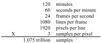
AbstractThe scope of compression techniques provided in the MPEG-2 toolkit is broad enough to meet today's picture quality expectations of digital cinema theatrical presentations with enhancements in rate control, 4:4:4 chroma format color space, and greater color precision than the profiles that are defined for television. This optimization for the unique requirements of digital cinema, while beyond currently defined MPEG profiles, is enabled by the wide range of the MPEG-2 toolkit and can be implemented using standard off-the-shelf silicon devices. Image compression is used in digital cinema distribution to make the visual content of the movie more practical to transport, store, and assemble. Each picture is represented by a set of numerical samples arranged in a raster. As uncompressed data, the volume would be large. For example, a digital cinema presentation with the typical resolution of year 2000 contains:
Each picture of the feature is crafted by the creative directors to tell the story, create a mood, and make an impression on the viewer using not only acting, camera placement, and special effects, but also such intangible elements as the precise choice of colors and the character of the film grain. Compression for digital cinema must preserve these elements, a stricter requirement than in other applications such as television where there is a more allowance for alteration of the image. It is evident that the widely used compression solutions conceived for CRT displays cannot deliver the high quality images that are enabled by the latest digital cinema display devices[1,2] projecting onto a large screen. This fact has fostered the development of altogether new compression algorithms. A wavelet based compression scheme[3] has been positively received by several Hollywood studios and thousands of viewers. Other innovative techniqes are in various stages of development[4]. Some or all of these new compression algorithms will be important for digital cinema, particularly when technology advances in resolution beyond the 1920 x 1080 limit imposed by current technology. However, the advanced approaches need further development to meet the requirements for widespead deployment. Specifically, there is a need for the compression algorithm to be based on a publicly available standard or specification to give assurance of conformance and interoperability. And devices must be available to provide realtime encoding and decoding. At the same time, it is possible to look deeper than the typical implementations of the most common incumbent compression technology, MPEG-2, to find a rich set of image compression tools that can be arranged in a new way to deliver cinema quality images. The MPEG-2 standard[5] is written on two planes. In the first, several compression tools are specified, including the block discrete-cosine-transform (DCT), quantization, variable length coding, and motion compensation. The standard establishes an unambiguous bitstream specification for all of these tools working together. In the second plane, profiles and levels are established that place constraints on which syntactic elements are allowed, which tools are used, and what limits are placed on parameters such as resolution and chroma format. The standard levels and profiles in MPEG-2 enable such applications as digital television and broadband internet video distribution. It is possible to use the MPEG-2 compression tools beyond the limits of the standard profiles and levels, effectively creating a new profile for digital cinema. Enhancements in three areas are needed to meet the quality expectations:
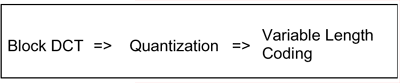
The following sections describe the enhancements as implemented using standard MPEG-2 silicon devices. Constant Quality Rate ControlMost common implementations of MPEG-2 are designed to work with some fixed bandwidth distribution channel. The 19.4 Mb/s payload of the ATSC digital television transmission standard is one example. These implementations apply a constant bit-rate control algorithm to the compression engine, to make sure that every picture can be delivered through the channel at the correct time. This type of rate control necessarily causes the picture quality after compression to vary from scene to scene. In digital cinema, the priority is for consistent picture quality from the first image to the last, before any requirement for fixed bandwidth transmission. Compression for digital cinema should use a variable bit-rate, constant quality mechanism for rate control. In fact, constant quality rate control is inherent to the basic set of compression tools of MPEG-2, listed in Figure 1. These operations naturally result in complex pictures being allocated more bits, and simple pictures less. The common practice to achieve a constant bit-rate involves adding a layer of control over these tools to monitor compressed picture sizes and adjust quantization for each picture. In compression for digital cinema, this control layer is disabled. The following paragraphs show how the basic MPEG-2 compression tools result in constant quality encoding.
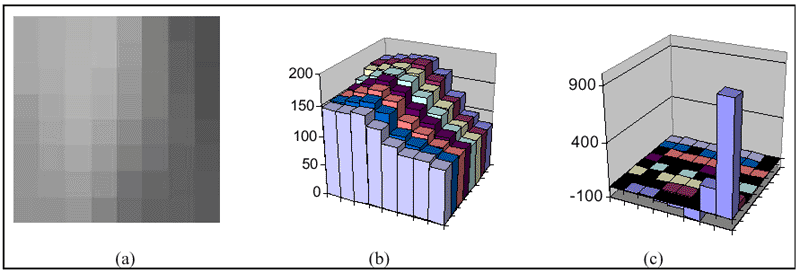
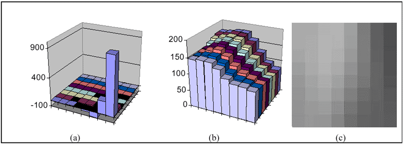
The DCT transforms the image data from the spatial domain to the frequency domain. As an example, the block of image data in Figure 2a,b is transformed to the DCT coefficients in Figure 2c.
At this stage no information from the original image data has been lost; taking the inverse DCT on the coefficient in Figure 2c exactly reproduces the original source data. The DCT coefficients are all signed 11- bit integers except for the dc term which is unsigned up to 11 bits. The advantage of the DCT transform is that most of the coefficients are zero, and many of the rest are small values. In the subsequent variable length coding operation, small values translate to short codes and zero values are run-length coded. It may seem reasonable to omit quantizing the DCT coefficients altogether and apply the run-length/variable-length codes on the DCT coefficients directly. The result is essentially lossless compression with about 2X compression ratio. Experiments have shown, however, that the human visual system is not sensitive to some quantization of the DCT coefficients[6]. In particular, those coefficients corresponding to the higher order basis functions (i.e. higher frequencies) may be quantized to a much greater degree than the dc or near-dc terms. The amount of quantization may be varied; this is the mechanism that provides constant quality rate control. The quantized coefficients QF[u,v] are computed from the DCT coefficients F[u,v], the quantization_scale, MQUANT, and a quantization_matrix, W[u,v], according to the following:
Figure 3a shows the normalized quantization factors W[u,v] with
The quantized coefficients QF[u,v] are shown in Figure 3b. The quantization step makes many of the values in the coefficient matrix zero, and it makes the rest smaller. The result is a a significant reduction in the number of coded bits with no visually apparent difference between the decoded output and the original source data.
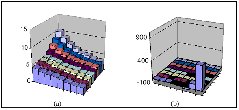
The DCT, quantization, and variable length coding steps are reversed in the decoder. The quantized DCT coefficients QF[u,v] are multiplied by the quantization factors. The result is the unquantized DCT coeffiencients Q'[u,v] in Figure 4a, slightly different compared to those before quantization in Figure 2c. The result of the inverse DCT is shown in Figure 4b,c, with only small differences compared to the original source block.
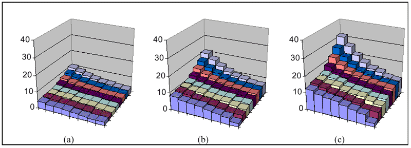
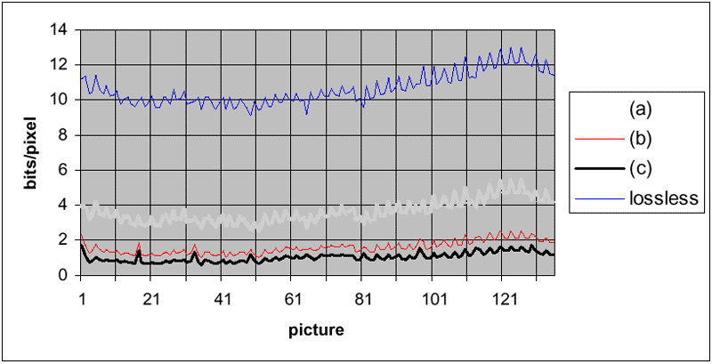
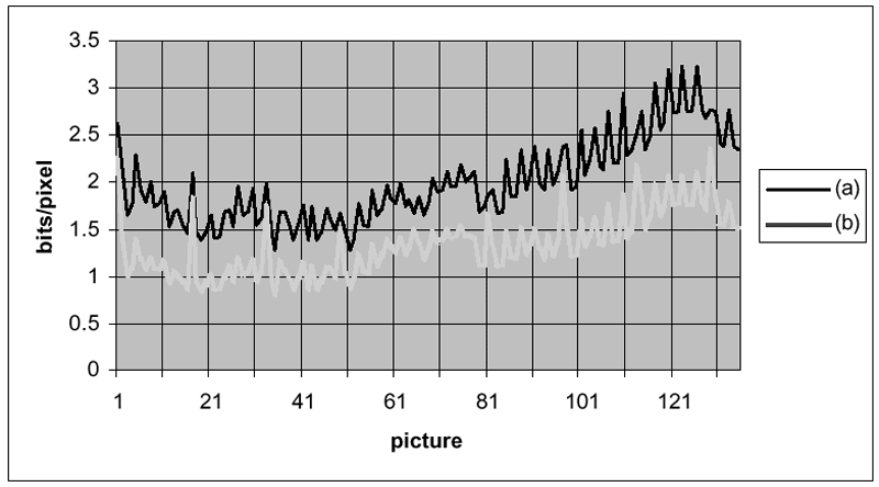
Some properties of the DCT and quantization operations are illustrated by the examples of Figure 2 and Figure 3. First, small quantization factors are appropriate for the lower frequency coefficients and larger factors are tolerable at higher frequencies, according to the human visual model. The dc value is only quantized by 2; the block carries 40-bit dc precision. These compression techniques apply to intra pictures in the MPEG-2 group of pictures (GOP) sequence. Intra pictures are independent and can reproduce the image without using data from another picture. In MPEG-2 there are also predicted pictures, which make reference both forwards and backwards to Intra pictures. For each block in a predicted picture, the encoder attempts to find a similar block in the reference picture. If successful, the encoder codes the motion vector describing any horizontal or vertical translation of the block between the reference and predicted pictures. It then calculates any remaining error between the source block and the predicted block and codes the error data using the same tools and techniques described above for intra blocks. If no close match is found for motion compensation, the encoder may code the block as an intra block, even in a picture that is supposed to be predicted in the group of pictures sequence. Motion compensation with predicted pictures is a powerful compression tool worth up to 2 - 5 times additional compression ratio; among the standard compression algorithms, only MPEG makes use of the technique. The number of coded bits representing the block depends on the quantization used, and this provides the mechanism for control. Figure 5 depicts three different normalized quantization matrices w[u,v]. Figure 5b and Figure 5c are the second and third multiples of the Figure 5a, except for the dc coefficient w[0,0] which does not vary; in other words the quantization_matrix W[u,v] is fixed while MQUANT = 2, 4, 6. These quantization matrices were applied to 136 frames of film content depicting a running figure in a moderate pan with a complex forest scene in the background. Figure 6 shows the average bits per pixel for the three levels of quantization, plus a fourth trace for lossless encoding using w[u,v] = 1 for all u,v.
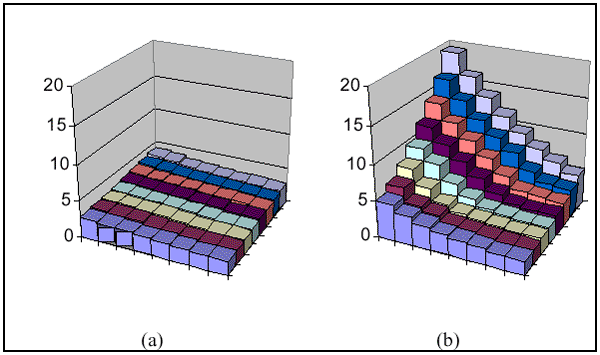
The sawtooth pattern in Figure 6 is the result of motion compensation. The higher values are intra pictures which are independently coded. Adjacent smaller values are predicted pictures based on motion compensation plus the coded difference picture from the reference Intra pictures. In Figure 6 there is also a general variation of up to 2X in bits per pixel over tens of frames. This is the constant quality rate control mechanism adapting to varying complexity from scene to scene. The mechanism works just as well for abrupt scene changes, even if they occur on a predicted picture making motion compensation ineffective. In that case, the encoder can code each block of the picture as if it were part of an intra picture; it is free to allocate as many bits as necessary to maintain quality according to the normalized quantization matrix w[u,v]. The quantization factors may be varied in another way. Figure 7 shows two other matrices, both with the same value at the near-dc coeffiecients but with different slope towards the higher frequency coefficients. In other words, the quantizer_scale is fixed at MQUANT = 2, and the quantization matrix W[u,v] varies. This method of quantization control also results in varying bits per pixel as seen in Figure 8.
Both methods of quantization control, like any lossy compression algorithm, will produce visible artifacts when carried to extreme values, but the nature of the artifact is different in the two cases. Excessively increasing the quantization factors by varying MQUANT as in Figure 5 leads towards 8x8 pixel blocking. Excessively increasing the slope of the quantization matrix W[u,v] as in Figure 7 leads towards high frequency noise, called mosquito noise, particularly on sharp, diagonal edges in the image. Neither artifact is acceptable for a digital cinema theatrical presentation; the best quantization control setting selects the largest MQUANT and the largest slope to the quantization matrix W[u,v] for which neither artifact is visible. The optimal setting will vary depending on the application, for example computer rendered, animated images versus telecine images, or based on the degree of horizontal squeeze, but it is expected to be a constant setting for the length of the feature. Constant quality rate control is an inherent characteristic of the DCT and quantization operations in MPEG-2, and direct access to the quantization factors is possible with many off-the-shelf standard silicon encoders. Despite this fact, virtually all MPEG-2 systems are designed with a more complicated, constant-quality rate control algorithm, and often do not allow the constant quality mode to be used. For the digital cinema application, disabling the constant bit-rate function and enabling constant quality encoding is an important enhancement beyond standard MPEG-2 implementations. Color SpaceIn digital cinema there is a requirement to represent the colors of the images as accurately as possible. This is another area where the standard levels and profiles of MPEG-2 fall short, but where enhancements are possible using the basic MPEG-2 tools. The standard levels and profiles of MPEG-2 mandate the use of the YCbCr color space and a chroma subsampling of either 4:2:2 or 4:2:0. Equal bandwidth color signals, or 4:4:4 chroma format, is appropriate for digital cinema for several reasons to be given below. It is possible to arrange the MPEG-2 compression tools in a different way to encode pictures using equal color bandwidth. The premise of chroma subsampling is that the human visual system has a lower spatial bandwidth for colors than for luminance; if the luminance signal contains frequency components up to the resolving capability of the eye, the chrominance signals may be band limited to lower frequencies with no visible degradation of the image. This model breaks down on the big screen, where the viewers are able to resolve details smaller than one pixel. Subsampling chrominance in this environment may lead to visible chrominance bleed on sharp edges. A sharp black to white edge may be lined with red, for example. This artifact is undesireable in digital cinema. Once in the equal color bandwidth space, there are several important reasons to encode RGB signals instead of YCbCr. Every coordinate in the RGB color space is a valid color. The YCbCr color space can be thought of as a rotation of the three color-space axes[7], yet it must still contain all valid colors, or the entire RGB cube, as shown in Figure 9. In YCbCr color space only 25% of the coordinates map to a visible color. The rest of the coordinates are invalid colors in that they map to an RGB coordinate with one or more negative values for R, G, and B. For a given bit depth the RGB space is more efficient; the 8 bit RGB color space has ~16.8 million unique colors compared to the 8 bit YCbCr which has only ~4.2 million visible colors. Current practice in digital cinema mastering uses SMPTE 292M interfaces between source material and the compression processor. This specifies a 10 bit YCbCr color space and 4:2:2 chroma subsampling. By converting the 10 bit YCbCr image data into equal color bandwidth RGB color space, one preserves more of the original colors compared to simply truncating to 8 bit YCbCr. There is strong motivation for all of the pieces of the digital cinema distribution chain to use equal color bandwidth. This is the fundamental colorspace of both the telecine where the digital image originates and the display device where the image is projected onto a screen. With the compression engine operating in the same color space, there is the opportunity to avoid performing colorspace conversions and to minimize the chance of introducing errors in the colors of the images. The DC28.2 study group on mastering for digital cinema is considering which colorspace is appropriate for the distribution master. The group may recommend RGB for both the compressed digital cinema distribution master media files and for the physical interfaces between components in the distribution chain[8].
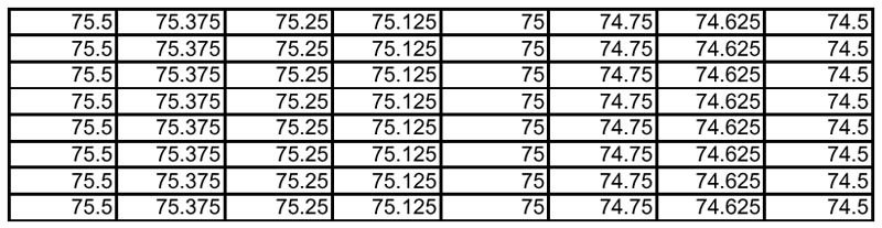
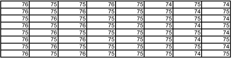
Error DiffusionIn some circumstances, accurate reproduction of the colors in an image may require greater bit depth than allowed by standard MPEG-2 implementations. The MPEG-2 standard supports 8-bit sample, and some images such as shallow ramps may exhibit banding or contouring artifacts. The problem is alleviated to some extent by using the RGB colorspace as discussed in the previous section. Where further enhancement is required, an error diffusion step may be applied. Error diffusion refers to a body of study in imaging where quantization error is accumulated and distributed about neighboring pixels[9]. The process is important for printed images, where bit depth can be as low as 1 to 4 bits per pixel, but the same principle may be applied to any case where there is a reduction of bit depth. Error diffusion is applied at the input to the encoder, where samples of greater depth are reduced. As an example, the image block with fractional values in Figure 10 is reduced to the 8-bit sample set without fractional values in Figure 11. The values over a small area vary by 1 to approximate the fractional values of the original sample set. The effect is to trade spatial resolution to a small degree in exchange for a greater effective bit depth.
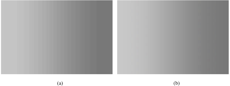
Visually, error diffusion noticeably reduces the banding artifacts characteristic to certain shallow ramps. Figure 12a shows a 6 bit RGB shallow ramp where banding is evident. Figure 12b shows the same 6 bit RGB shallow ramp with error diffusion applied. The banding is clearly reduced if not eliminated. 6 bits of depth was used in this demonstration to exaggerate the effect of banding on the printed page.
Standards BasisThe application of the standards-based MPEG-2 tools to the digital cinema application provides several key success factors. The MPEG-2 bitstream syntax is completely specified in the standard. This allows the correctness of the bitstream to be checked and it ensures that a correct bitstream can be decoded by a compliant decoder. One of the five sections of the MPEG-2 standard is devoted to conformance testing. The basic elements of correctness of the bitstream, conformance testing, and interoperability are essential to the successful deployment of any compression algorithm for content distribution. Another success factor comes from the deep penetration of MPEG-2 into many different market segments. Because there are so many manufacturers creating MPEG-based devices, component pricing has reached commodity levels, especially for decoders. Multiple sources for compatible components also give end users the assurance of not being dependent on any one supplier. The wide use of MPEG-2 also provides flexibility to make different types of content available for presentation. Non-cinema content such as interstitials may be produced using the standard MPEG-2 main profile @ high level and handled by the same decoder technology as cinema content encoded using the extension described in this paper. In time one may expect the new advanced compression algorithms mentioned in the introduction to become available with their own publicly available standards basis and many of the same success factors as the MPEG-2 based approach. The MPEG standards-making organization has made public a draft call for proposals[10] open to any algorithm in an effort to standardize a new compression algorithm specifically adapted to the requirements of digital cinema. If this organization is successful in standardizing a new algorithm in the next two years, there is the promise for an "easy transcode" capability from MPEG-2 to the new compression algorithm. This may provide a path for compatibility in the new standard for legacy distribution masters that were created using the MPEG-2 compression tools. ConclusionMPEG-2 is dismissed by many as inappropriate for digital cinema since it is often viewed at high compression ratio in low bit-rate applications. But MPEG-2 is fundamentally a rich set of compression tools, with capabilities that are not made available by the commonly defined profiles and levels. By looking deeper than the usual implementations of the standard it is possible to find enhancements to enable the high picture quality required by the digital cinema application. Enhancements in constant quality rate control, color space, and bit depth are possible while still adhering to the basic MPEG-2 bitstream specification. The enhancements work together with the same silicon devices that are used in larger markets, allowing digital cinema to take advantage of the beneficial price/performance ratio in the compression and playback systems. References
|
|
|
|||||||||||||||||||||||||||